In the field of aerospace vehicle research and development and manufacturing, structurally complex components are extremely difficult to process in the traditional way, and the productivity and yield are low and the cost is high, and even overly complex components cannot be processed. With the rapid development and application of 3D printing technology, refractory alloy complex high-temperature components in the field of aerospace, supersonic vehicles have also begun to use 3D printing technology manufacturing [1]. 3D printing technology is a rapid prototyping technology, it is a digital model file as the basis for the use of powdered metal or plastic and other bonding materials, through the way of the layer-by-layer printing to construct the object of the technology, production efficiency, Product precision, shape can be complicated, manufacturing is not affected by the complexity of components and has a unique lightweight manufacturing characteristics. 3D printing manufacturing can effectively reduce the difficulty of manufacturing, reduce material consumption, reduce costs, and reduce the weight, which can effectively achieve the lightweight of the aircraft [2]. Due to the 3D printing refractory alloy components in the high temperature environment, there are still oxidation problems, the component surface needs to be antioxidant protection treatment [3].
Due to the differences between the organisational structure of 3D printed refractory alloys and that of traditional pressure-processed alloys, the high-temperature antioxidant coatings prepared on the surface of 3D printed refractory alloys using existing coating materials and preparation techniques have a very short lifespan, and are unable to meet the engine's operating requirements. The research on the preparation of high-temperature antioxidant coatings on the surface of 3D printed refractory alloys is still blank in China.
Ta10W combined metal refractory high-temperature alloy, the alloy has excellent high-temperature mechanical properties, the application temperature up to 1600 ~ 1900 ℃, is currently a new generation of refractory high-temperature alloys ideal aerospace materials, in the aerospace, supersonic vehicles began to be applied in the field, in order to meet the application of high-temperature components in the engine of the 3D printing Ta10W alloy, it is necessary to 3D printing of the Ta10W alloy coating materials and preparation technology research, to solve the problem of high temperature antioxidant coatings. and preparation technology research, to solve the 3D printing Ta10W alloy in 1600 ~ 1900 ℃ key oxidation problems, to achieve the 3D printing TaW10 alloy in the application of ultra-high temperature engine [4-5].
1 test
1.1 Coating preparation
The substrate with 3D printing Ta10W alloy structural parts, the main component is 90Ta-10W, after the outer surface sandblasting - pickling - washing - drying pretreatment to be used.
Coating with a silicide system, Si, Mo, Cr, Ti and other powders according to a certain mass ratio of preparation and mixing into the ball milling tank, and add a certain amount of organic solvents in the tank; the ball milling tank into the ball mill for mixing and grinding coating slurry, ball milling slurry uniformly coated on the surface of 3D printing Ta10W alloy structural parts, drying in a vacuum furnace sintering to produce a 3D printing Ta10W alloy coated structural parts [6], as shown in Figure 1.

Figure 1 3D printed Ta10W alloy coated structural parts
Process route: 3D printing Ta10W alloy structural parts → sand blasting → pickling → Si, Mo, Cr, Ti and other coating powder mixture → adding organic solvents → ball milling → coating slurry → coating → vacuum sintering → coating products.
1.2 Test run of coated structural parts
The 3D printed Ta10W alloy coated structural parts are installed on the thermal assessment test bench, the structural parts are hollow tubular structure inside, the test process tube is pressurised to 6MPa by passing coolant into the tube, and electrically heated by using low-voltage, high-current endothermic method. With colorimetric thermometer, two-colour infrared thermometer and thermocouple wire for working temperature determination [7-8]. The test was stopped after the coated structural parts worked at 1800°C for 350s.
2 Results and analyses
A comprehensive inspection of the 3D printed Ta10W alloy coated structural parts after the test revealed that the outer surface coating and matrix structure of the structural parts were intact, and the local area inside the tube was found to have a smaller diameter by high-energy CT transmittance, as shown in Figure 2.

Fig. 2 High-energy CT transmission inside the tube after the test
To analyse and study the phenomenon of local pipe diameter reduction in the tube after 3D printing of Ta10W alloy coated structural parts. The 3D printed Ta10W alloy coated structural parts after the test were planed, and after planing, it was found that there were accumulations in the ring area, as shown in Figure 3.

Fig. 3 Planing of coated structural parts after test

Fig. 4 SEM cross-section of the area where there is an accumulation of material
From Fig. 4, it can be seen that the coating is visible on both edges of the outer surface of the structural member from the outside to the inside, and the thickness of the coating is uniform, as shown in Fig. 4.(a) and other parts. The area (b) in Fig. 4 is the substrate of the structural member. Figure 4 (c, d) region for the internal part of the runner, (b) and (c) can be seen between the substrate and the runner inside the accumulation of material demarcation line, but the thickness of the runner inside the accumulation of material is obviously greater than the thickness of the coating, the structure of the presence of holes, and the inner wall surface unevenness, indicating that this region of the runner inside the wall surface of the coating has been destroyed by the substrate has been eroded. In Fig. 4, (d) shows the filler added in the runner during SEM sampling. To analyse the possible reasons, due to the coating peeling off at high temperature and pressure, the substrate reacted with the CO2 gas passed inside the runner at high temperature, and the presumed chemical equation is.
5CO2+2Ta=Ta2O5+5CO
Accumulator in the runner may be Ta2O5 [9-10].
2.2 Accumulator EDS analysis
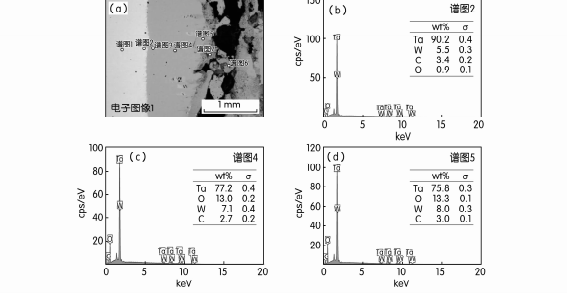
Elemental analyses were performed by EDS for the region where the accumulations existed, as shown in Fig. 5.
EDS elemental composition analysis in Fig. 5(a) shows that the elemental content of Ta reaches 90.2%, W 5.5%, C 3.4% and O 0.9% in the boundary region between the matrix and the accretion Fig. 5(b). The middle region of the accumulation, Fig. 5(c), reaches more than 77.2 per cent Ta, 7.1 per cent W, 13.0 per cent O, and 2.7 per cent C. The middle region of the accumulation, Fig. 5(d), has an elemental content of more than 77.2 per cent, 7.1 per cent W, 13.0 per cent O, and 2.7 per cent C. The outer edge region of the accumulation, Fig. 5(d), has 75.8% Ta, 8.0% W, 13.3% O, and 3.0% C. The elemental analysis of the outer edge region of the accumulation shows that the elemental analysis of the outer edge region of the accumulation reaches more than 77.2%, 7.1% W, 13.0% O, and 3.7% C. Through the accumulation of different areas of elemental analysis, are not detected coating components, and the accumulation of regional elemental body are the main components of the matrix elements Ta and W, indicating that in the high temperature and high pressure, the coating has been peeled off by the high-pressure gas-liquid flow washed away, the substrate loses its protection, and at high temperatures were eroded to spall off the formation of the accumulation of material.
2.3 EDS analysis of the coating in the incompletely damaged area
Elemental analysis of the coating in the incompletely damaged area was carried out by EDS, as shown in Figure 6.
The SEM image in Fig. 6(a) shows that the coating structure is clearly visible, and the elemental composition analysis by EDS shows that the content of Si element in the region of Fig. 6(b) is 24.2%, the content of Ta element is 70.0%, the content of W element is 2.2%, and the content of C element is 3.6%. The region of Fig. 6(c) has 8.5% of Si element, 83.1% of Ta element, 4.6% of W element, 0.8% of Cr element, and 3.0% of C element. O element content is not detected in both Fig. 6(b and c), but Si and Cr coating composition elements are detected, due to the high temperature diffusion of Ta and W elements in the substrate infiltrated into the coating. However, the structure of the coating has not been completely destroyed, and still plays a protective role for the substrate.

Fig. 5 EDS elemental composition analysis of the cumulative material

Fig. 6 EDS elemental composition analysis of the coating in the not completely damaged area.
2.4 Analysis of the causes of coating spalling
Ta10W alloy structural parts are moulded by 3D laser selective printing, laser selective melting forming technology is one of the industrialization directions of 3D printing focusing on the development of the technology (also known as selective laser melting Se-lectiveLaserMelting, SLM) is based on the basic idea of rapid prototyping, i.e., point-by-point, layer-by-layer melting of the additive manufacturing method, according to the three-dimensional model of the part Based on the three-dimensional model of the part, the model is sliced in layers of a certain thickness, and the three-dimensional shape information of the part is converted into a series of two-dimensional contour information, and then under the control of a numerical control system, the laser is controlled by an array of mirrors to melt the metal powder, and the part with a specific geometric shape is formed directly [11].
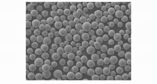
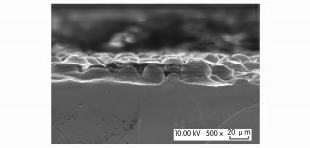
Since Ta10W alloy structural parts are printed using spherical powder as shown in Fig. 7, the surface of the printed part is rough and uneven as shown in Fig. 8. After printing the structure of the outer surface can be sandblasted, polished and other methods to deal with clean, but for the small diameter tube wall surface can not be effectively dealt with clean, pickling can only achieve the role of cleaning the surface, can not improve the degree of surface roughness, the coating preparation of the tube wall surface is still rough and uneven surface, resulting in the coating and the substrate can not be achieved between the metallurgical bonding of the state of the substrate, resulting in the coating and the substrate is not solid, in the high temperature under a certain pressure of impact liquid flow. At high temperatures by a certain pressure liquid impact so that the coating gradually peeled off, the substrate to lose the protective effect of the loss of coating protection of the substrate at high temperatures and high pressures subjected to gas-liquid erosion layer by layer peeling off the accumulation of the formation of accumulations [12 -13].

Fig. 7 3D printed spherical powder

Figure 8 3D printed Ta10W alloy structure surface
3 Conclusion
Coating as a part of the surface of the service carrier, in the external thermal corrosion, thermal gradient stress and mechanical load stress, easy to surface cracking and interface coating spalling, when the coating interface at a certain location of the maximum adhesion density is less than the inertial force density of the coating movement, the interface will be de-bonded. Coating interface first in the inertia force density of the largest debonding, and then debonding area along the radial expansion caused by the coating spalling. Because the bottom surface of the coating before peeling and the substrate ideal adhesion, and 3D printing Ta10W alloy printing using spherical powder, after printing the surface roughness, the preparation of high-temperature antioxidant protective coatings, the coating and the substrate can not form an effective metallurgical bond between the coating and the substrate and the bonding surface of the coating structure loose, resulting in the coating and the substrate between the bonding strength is not enough. Due to the differences between the coating material and the substrate material in mechanical, thermal and other properties, under the action of different loads, the coating interface deformation is not coordinated, the coating and the substrate combination strength is not enough, resulting in stress so that the coating interface debonding, with the thermal effect and load increase, resulting in the expansion of the debonding led to coating spalling, loss of protection substrate erosion stripping, and ultimately lead to the failure of the structure or parts.
Reference:Ta10W material 3D printing process research - BaiduWenku (baidu.com)
The spherical tantalum powder prepared by Stardust Technology using RF plasma spheroidisation technology has high purity and low oxygen, high sphericity, smooth surface, no satellite balls, uniform particle size distribution, excellent flow properties and high bulk density and vibration density, excellent biocompatibility, and the tantalum implant shaped by 3D printing has the elastic modulus closest to that of the human cartilage tissue, which is the most ideal orthopaedic implantation It is the most ideal orthopaedic implant material. Our spherical tantalum powder fully meets the standards of YY/T 0966-2014, ISO13782:1996 and other standards in the field of medical implantation.
Welcome to contact us, Manager Zheng 13318326187.
