
0 Introduction
With the continuous development of China's aerospace and missile weapons field, the surface of the material to meet the high-temperature mechanical properties, good thermal corrosion performance and resistance to high-temperature oxidation performance of high-temperature coating requirements are increasing. Existing high-temperature alloys and coating preparation technology after decades of scientific research and improvement, the coating system tends to be perfect, the use of temperature increase is facing a more difficult challenge than ever. Refractory metals that can be used in the aerospace field include tantalum, niobium, tungsten, molybdenum and rhenium. Tantalum-based alloys have higher heat-resistant temperatures and stress loads than niobium-based alloys, and the use temperature of tantalum-based alloys can reach more than 1,800°C with the addition of other refractory metals, but their thermal shock performance is still a major problem, and there are fewer articles on high-temperature oxidation-resistant coatings for Ta10w alloys. In this environment, the authors of this paper hope to achieve the purpose of improving the use temperature of high temperature antioxidant coatings through the method of this paper.
Among the existing base materials, Ta10w alloy has high high-temperature strength, good mechanical properties, weldable, ductile, corrosion-resistant and impact-resistant. Melting point 3080 ℃ [1, 2], but its high-temperature antioxidant performance is poor, in the absence of protective measures, Ta10w alloy and other high-temperature alloys, as in the case of 500 ℃ will appear ‘pest’ oxidation phenomenon. In the high-temperature alloy surface with high-temperature antioxidant coating can significantly improve the alloy's high-temperature oxidation resistance, but also to retain the alloy's high-temperature strength to the maximum extent, the high-temperature alloy oxidation at high temperatures to form a good protection.Ta10w with its excellent high-temperature performance is widely used in aerospace, weapons and missiles, shipbuilding industry and other fields [3-5], such as the U.S. Ajina spacecraft combustion chamber made of this alloy [6], the domestic research based on this alloy is still relatively small, so it is necessary to carry out such research.
The purpose of this paper is to use another method for the double glow plasma penetration plating technology, which is characterised by the formation of the surface alloying layer and the substrate for the metallurgical bonding, high bonding strength, dense organisation, no porosity, cracks and other defects in the thickness of the alloy layer is controllable, the maximum of up to 300 μm or more [7]. The preparation process is simple, low cost, and can handle tantalum products with complex shapes, the high temperature coating transition layer prepared by this method is very dense, the main manifestation of the existing high-performance high-temperature protective coatings thermal shock failure is that with the prolongation of the test time, resulting in cracks through the surface of the coating to the surface of the substrate, so that the substrate quickly oxidised, this paper expects to use the method of this paper to prepare a layer of the transition layer attached to the surface of the substrate, so that it can effectively prevent the penetrating cracks extend to the surface of the substrate, so as to achieve the effect of high temperature protection.
1 test
Add a layer of metal modification between Ta10w alloy and coating. Purpose: ① to change the main component of the existing bonding layer from hard and brittle Ta-Si coating to other better thermal shock resistance M-Si coating; ② the use of the plasticity and ductility of the metal to offset, buffer coating and alloy due to poor thermal matching of thermal stresses, so as to maintain the structural integrity of the coating is not cracked. The matrix used in the test is Ta10w alloy, the composition is shown in Table 1, melting point 3080 ℃, density 16.9g/cm3, hardness 240kg/mm2, impact toughness 630kJ/m2, 1800 ℃, σb>110MPa, σ0.2>75MPa, δ>30%, ψ>85%, Et181GPa.
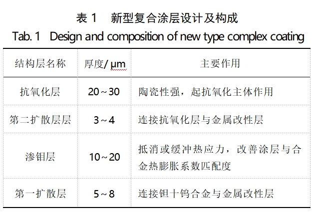
The Mo-based coating was prepared on the surface of the substrate (70 mm × 8 mm × 1 mm) by using the double glow iontophoresis plating technique, and the silicide coating was applied on top of the Mo-based coating. The specimen preparation process is shown in Fig. 1. The double glow ion plating process is vacuum 1.0×10⁻² ~ 1.0×10⁻³, cathode voltage 400-500V, source (molybdenum target) voltage 1100-1300V, metal target is molybdenum target, the specimen is a Ta10w sample (70mm×8mm×1mm), the working air pressure 20-80Pa In order to reduce the molybdenum metal ions escape during the penetration plating, the heat insulation basket is placed outside the specimen basket, and the cover plate is added on the top, the cathode voltage is kept constant during the penetration plating process, and the temperature and working pressure are adjusted to use the glow discharge to ionise the argon gas, and the ionised argon ions bombard the molybdenum target material under the action of the electric field to sputter out molybdenum ions, which are released under the negative pressure. Molybdenum ions, molybdenum ions into the specimen alloy surface to form an alloy layer under the action of negative pressure. The process because the anode and the source pole, cathode, respectively, the occurrence of glow discharge, so called double glow, and finally get the molybdenum coating thickness of 20μm, the surface is flat and smooth, no holes.
In the molybdenum infiltration layer coated with silicide coating, silicide coating slurry in the configuration of the main powder used for Si50% ~ 90%, Mo1% ~ 20%, Ti1% ~ 20%, Zr1% ~ 20%, Y2O3, 0.1% ~ 5%, TiB21% ~ 20%, the thickness of the silicide coating of 80~150 μm, the silicide coating coated directly on the molybdenum system coating, the use of high-vacuum The silicide coating was directly coated on the molybdenum coating, and the slurry was made by high vacuum fusion burning, using corundum ball milling jars, ethanol solvent, and a rotating speed of 300r/min for 6h. A slurry amount of 0.26 ~ 0.28g, the second 0.14 ~ 0.16g, one or two vacuum melting and burning process for 1350 ~ 1520 ℃, insulation time of 15 ~ 25min, the thickness of the resulting silicide coating in the 80 ~ 150 μm.

Fig. 1 Flow of composite coating preparation
The chemical composition of the Ta10w alloy used is shown in Table 2 below.

2 Performance testing methods
High-temperature performance testing of the prepared composite coating, the testing method for a long time at a fixed temperature static testing and repeated warming and cooling to a specific temperature, heat preservation, cooling thermal shock detection. The test bench adopts copper electrodes, heated by electric current and cooled by circulating water, the temperature measurement method adopts two-colour infrared thermometer, and the whole test is recorded by computer to record the test temperature and other data.
The static test is under atmospheric conditions for about 30s to rise to the specified temperature, insulation until failure.
Thermal shock test in the atmosphere about 18s to the specified temperature, insulation about 10s, cooling about 20s, cooling to room temperature, and then cycle the whole process, the whole process is carried out by a special high-temperature test bench, the test bench is equipped with a timer and counter, just set the temperature, insulation, cooling time click on the run, the program can automatically run until the test site through the wearing of high-temperature protective goggles observed to the test piece failure and stop. Stop after the failure of the specimen.
Static and thermal shock performance failure is judged to be, wearing protective goggles to observe, the specimen appeared visually visible black spots, cracks, bumps and so on. In order to characterise the high-temperature oxidation resistance of the composite coating, the thermal shock and static performance are selected 1800 ℃ test, the test data are shown in Table 3.
3 Results and Discussion
3.1 Double glow ion plating molybdenum coating

Fig. 2 Macroscopic morphology of molybdenum layer prepared by double faience ion plating (top) versus Ta10w alloy surface (bottom).
Figure 2 can be seen from the penetration of Mo layer is bright silver, metallic, and tantalum ten tungsten alloy combined tightly, the surface is smooth and flat visible to the naked eye without cracks, holes, bulging and other defects exist, Ta10W alloy surface is more bright some.
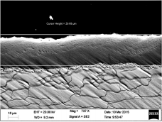
Fig. 3 Cross-sectional morphology of bifacial iontophoresis molybdenum coating
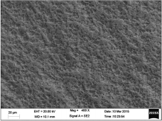
Fig. 4 Surface morphology of bifacial iontophoresis molybdenum coating
As shown in Figure 3 the molybdenum infiltration coating on the surface of the substrate is about 22 μm, dense and uniform, and the surface alloying layer is known to be a gradient material by the technical characteristics of the double-flare ion plating, which is firmly combined with the substrate. The alloy layer is formed by elemental diffusion, and the composition and properties of the layer are gradient distributed with depth. There is no interface between this alloy layer and the substrate with sudden change in performance, and the substrate for metallurgical bonding, not easy to peel off. In the figure, the substrate cracked because the molybdenum process in the commissioning period, the voltage is high, bombardment of the substrate surface to make it cracked, and because of the molybdenum temperature is not appropriate, resulting in the growth of substrate grains, adjusted after the substrate is no longer cracked, the subsequent SEM image can be seen, this figure is only as a demonstration of the degree of density of molybdenum infiltration layer. Figure 4 shows that the molybdenum layer surface without porosity cracks and other defects, dense and uniform can effectively protect the substrate oxidation [8-10]. In the deposition process, the collision between the plasma generates a large amount of heat.
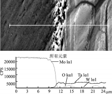
Fig. 5 Compositional analysis of double glow ion-diffusion molybdenum coating
Target, and substrate are raised to a higher temperature (800-900°C). During this process, there is a thermal diffusion process between the coating, the coating/substrate co-mingled zone, and the substrate, while at the same time, due to the sputtering of the substrate, many vacancy defects are generated on the substrate surface, which leads to a decrease in the diffusion potential between the elements, and the easy diffusion between the elements. The existence of the diffusion process makes the width of the co-mingled zone expand further, which improves the bonding strength of the coating and the substrate at the same time, and also improves the thermal expansion matching between the coating and the substrate.
3.2 Silicide coating on molybdenum infiltration coating
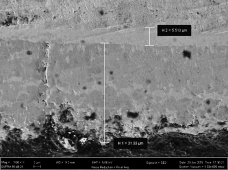
Fig. 6 Cross-sectional morphology of silicide coating on molybdenum layer
As shown in Figure 6, the total thickness of the composite coating is about 35 μm, the molybdenum layer is 5 μm and the silicide coating is 31 μm, and the thickness of most of the composite coatings in the later tests is about 100 μm, which can improve the high temperature capability of the substrate more effectively. The surface layer of silicide coating than the molybdenum layer is slightly loose, at high temperatures is a molten state, with mobility, can effectively fill the coating volatilisation when the formation of holes and cracks, to improve the coating life [11-14]. In this paper, the experimental performance testing of the composite coating thickness of 80 μm or more, the coating thickness is shown in Table 3.
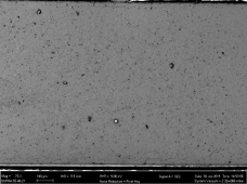
Fig. 7 Surface morphology of silicide coating on molybdenum layer
3.3 High temperature performance of composite coatings
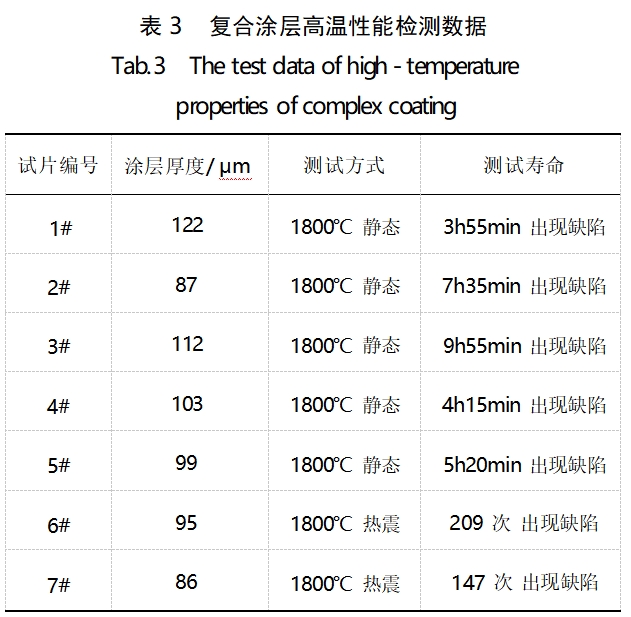
In the high temperature performance test, the static life at 1800℃ can reach about 10h, and the thermal shock performance is about 200 times. Figure 8 shows the EDS of the composite coating after thermal shock failure, from which it can be seen that there are a lot of cracks in the silicide coating on the molybdenum layer of the biflourescent iontophoretic plating, there are two kinds of longitudinal and transversal, and the longitudinal cracks have a depth of about 70 μm, which run through the surface of the coating and reach the molybdenum layer directly, and the bonding force between the molybdenum and the silicide coating has been formed. Diffusion layer is formed between the molybdenum layer and the silicide coating, which improves the bonding force between the two layers, and improves the thermal cracking caused by the different coefficients of thermal expansion, and the molybdenum layer (the right part in the figure, this part is not an alloy substrate, and the substrate and molybdenum layer part is given in the following figure) is still dense and uniform, and it is a good barrier to Si and O2, and it has a protective effect [15, 16], and it can be seen that the coating failure manifests itself as a surface failure, and the next step is to consider from the improvement of the surface performance, and it can be seen that there are still a lot of improvement in this composite coating. The composite coating still has a lot of room for improvement.
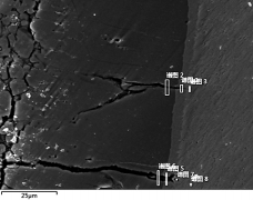
Fig. 8 EDS morphology of the cross-section of the second diffusion layer after thermal shock at 1800℃.
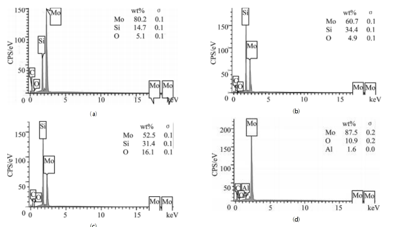
Fig. 9 EDS elemental content of cross section of silicide coating on molybdenum layer
Figure (a) can be seen from the double glow ion molybdenum layer and the formation of a diffusion layer between the silicide coating, the diffusion layer is mainly composed of molybdenum (80.2%), followed by silicon (14.7%); (b), (c) can be seen as long as the elements within the cracks for silicon (50%), followed by molybdenum (30%) and a small amount of oxygen (15%); Figure (d) is the molybdenum infiltrated layer, the main component is molybdenum.
Thermal shock after the molybdenum layer cross-section EDS point scanning morphology as shown in the figure coating part of the dense and uniform, in the transition between the coating and the metal part of the cracks, the analysis is considered to be by the double glow ion plating process substrate surface bombarded by the microcracks occurring in the high-temperature testing process due to thermal expansion caused by [17-19].
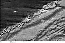
Fig. 10 EDS elemental content of the first diffusion layer cross-section
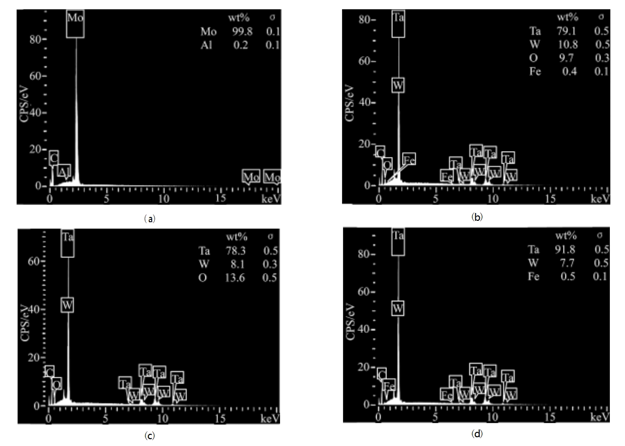
Fig. 11 EDS elemental content of the cross-section of the silicide coating on the molybdenum layer
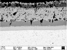
From Fig. (a), it can be seen that the main element of the bifacial ion molybdenum layer is molybdenum (99.8%), and from Figs. (b, c, and d), it can be seen that the transition layer between the molybdenum layer and the substrate is composed of the substrate material, and the cracks below the molybdenum layer are composed of the substrate material, and the main substances of the substrate material are Ta, and W. The molybdenum layer is on the left side of the figure, and the substrate is on the right side, and the longitudinal cracks of the silicide coating do not go through the molybdenum layer as shown in the figure, therefore the substrate is not exposed to atmospheric oxidation during high temperature oxidation, so that it can effectively stop the substrate from oxidation. The longitudinal cracks in the silicide coating do not pass through the molybdenum layer as seen in the figure, so the substrate is not exposed to the atmosphere and oxidised during the high temperature oxidation process.
(a)
(b)
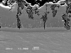
Fig. 12 Comparison of conventional silicide coating and composite coating in this paper
The above figure a is the conventional silicide coating, b is the composite coating in this paper, it can be seen that the longitudinal cracks in the left figure has penetrated to the substrate, in the high temperature test process is very easy to substrate oxidation failure, b figure although the surface coating has failed, but the longitudinal cracks and holes can not penetrate through the molybdenum infiltration layer to reach the surface of the substrate, so the use of molybdenum infiltration layer in this paper for the purpose of improving the service life of high temperature of the substrate has a prominent role.
The improvement of the thermal shock properties of the coatings described herein can be considered from the following points of view.
1) In the selection of the silicide coating, select the existing coating formula with high thermal shock performance, and add metal oxides with a coefficient of thermal expansion close to that of the transition layer of molybdenum metal.
2) Add nanoscale B-type, Zr-type, SiC fibre and other powders to the coating formula for trial.
3) Use rare earth elements to prepare ceramic layer for heat insulation to reduce the fatigue of the coating due to hot and cold alternation.
Most of the high-temperature oxidation coating failure is due to a large difference in the coefficient of thermal expansion leading to high-temperature cracking of the coating, cracks to make the coating failure, the composite coatings prepared in this paper because of the full consideration of the impact of the coefficient of thermal expansion of the coating performance, by doping a variety of coefficient of thermal expansion of the substrate and the substrate (5.53-7.29 × 10⁻⁶ / ℃, 100-1300 ℃) closer to the Additives, so the layer and layer, layer and substrate thermal match between the better, no cracks due to the difference in the coefficient of thermal expansion bulging.
4 Conclusion
1) The Ta10w high-temperature oxidation-resistant composite gradient coating prepared by double glow ionic molybdenum infiltration technology and slurry melting and burning method can work continuously for 10h at 1800℃, and there are diffusion layers of varying thicknesses between molybdenum infiltration layer and substrate, and between silicide coating and molybdenum infiltration layer, which enhances the bonding strength of the coatings, and effectively improves the coatings' high-temperature resistance performance.
2) The thickness of the molybdenum layer prepared by the double glow ion plating technology is controllable, dense and uniform, and the molybdenum infiltration layer is still dense and uniform after the surface layer fails after 10h of continuous work at 1800℃, which effectively protects the substrate material.
3) The composite coating obtained by the method of this paper effectively blocked the penetration of longitudinal cracks to the surface of the substrate.
Reference:The Complex High Temperature Oxidation Resistant Coating for New Type Ta10W Alloy for Aerospace Purposes - CNKI
Ta-10.0W alloy powder is an alloy of tantalum (Ta) and tungsten (W) and is typically used in high temperature and high strength applications such as in the aerospace or chemical industries. Alloy powders can often be used in areas such as 3D printing, powder metallurgy or coatings. Such spherical alloy powders may have high flowability and homogeneity, which helps in the preparation of complex shaped parts or coatings. Such materials may excel in high temperatures, corrosion resistance, etc.
The spherical Ta10W alloy powder prepared by Stardust Technology using RF plasma spheroidisation features high purity, very few satellite particles, smooth surface, uniform particle size distribution, low oxygen content and excellent flow properties. It is especially suitable for additive manufacturing, 3d printing, laser/electron beam selective zone melting, laser cladding, hot isostatic pressing and other processes.
Hotline: +86 13318326187 Zheng Manager
