
1 Introduction
Refractory metals such as tantalum (Ta) and tungsten (W) and their alloys have excellent physical and chemical properties such as high density, high melting point, good processing performance and resistance to molten metal corrosion. They are widely used in the fields of electronics, weapons manufacturing, aerospace and nuclear industry, and occupy an important position in the national economy and national defense science and technology. Among them, the crystal structure of tantalum (Ta) and tungsten (W) is body-centered cubic (BCC) structure, which can form a binary continuous solid solution alloy . This refractory alloy uses tantalum as solvent and tungsten as solute, and is generally made by vacuum electron beam melting or powder metallurgy. In addition, in addition to the above advantages of refractory alloys, Ta-10W alloy also has the advantages of high high temperature strength, good thermal shock resistance and small linear expansion coefficient. It is particularly suitable for the preparation of key components serving in the aerospace field under extremely high heat conditions.
At present, the welding of tantalum-tungsten alloys is often completed by argon arc welding, vacuum diffusion welding and vacuum electron beam welding. Ding Xu achieved the connection of Ta-12W alloy by argon arc welding. Due to the high heat input, the weld grains are large and the grains in the heat-affected zone are severely coarsened; the tensile test shows that the specimen breaks in the heat-affected zone with a strength of 438 MPa. Tao et al. used a vacuum electron beam process to achieve the welding of Ta-10W and GH3128, and carried out post-weld solution treatment; the study showed that solution treatment can effectively eliminate microcracks in the joint and allow the elements to diffuse fully, the weld structure changes from dendrites to blocky austenite, and a large amount of alloy carbides are precipitated. Chen et al. studied the electron beam welding of pure tantalum and pure tungsten and found that the weld was poorly formed, there were a large number of cracks and shrinkage cavities inside the joint, and the strength was only 56 MPa; the method of biasing the electron beam action position toward the Ta parent material was used for welding, and a weld with good formation and organization was obtained. In addition, the team studied the electron beam butt welding process of TC4 and Ta-12W dissimilar materials and found that when the electron beam was biased toward the TC4 parent material by 0.4 mm, the joint strength was basically equal to the strength of the tantalum-tungsten alloy parent material, and free elemental tantalum existed in the weld. Luo et al. [11] used Ni foil as the intermediate layer and achieved the connection between 93W and Ta by vacuum diffusion welding. The joint strength was 202MPa. The joint broke at the Ni-Ta interface. The fracture mode was ductile fracture. A large number of intermetallic compounds such as Ni4W, Ni2Ta and Ni3Ta were formed on the fracture interface.
Compared with CO2 laser, fiber laser has outstanding advantages such as high material absorption rate, high processing flexibility and high operation stability. It is widely used in the processing of high-reflection, high-heat strength and high-melting point materials such as aluminum alloy, high-temperature alloy and ceramic materials. However, since it is usually implemented in an atmospheric environment, fiber laser welding has the characteristics of large molten pool fluctuation, high plume eruption speed and large welding spatter [18-19]. In addition, Ta-10W has poor gas compatibility and is extremely sensitive to impurity elements. The alloy begins to absorb oxygen at 300°C, hydrogen at 340°C and nitrogen at 700°C, which seriously affects its mechanical properties and high-temperature processing performance [1]. This poses a severe challenge to the Ta-10W fiber laser welding process.
This paper studies the influence of welding power and welding speed on weld morphology by performing fiber laser scanning welding and butt welding on Ta-10W alloy plates, and obtains the power threshold when thermal conduction welding is transformed into deep melting welding. In addition, the weld morphology and microstructure of a-10W butt joints were observed, and the microhardness and tensile mechanical properties of the joints were tested, and the fracture morphology and fracture characteristics were analyzed.
2 Test methods and equipment
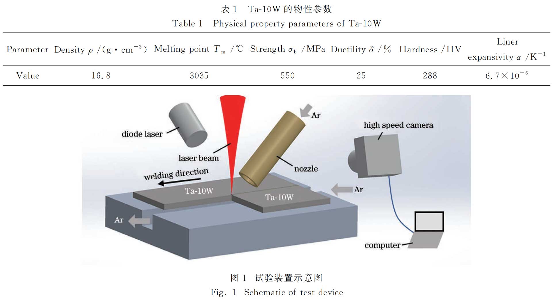
The test material is a Ta-10W refractory alloy plate melted by vacuum electron beam, and its structure is mainly a single-phase tantalum-tungsten solid solution. The physical properties of the material are shown in Table 1. The test equipment is a YLS-6000 multimode fiber laser, with a beam wavelength of 1060~1070nm, a beam focusing parameter f=
8mm·mrad, a transmission fiber core diameter of 200μm, a focal length of the output coupling collimator of 200mm, a focal length of the focusing lens of 300mm, and a focusing spot diameter of 0.3mm. A five-axis three-dimensional machining platform is used to control the motion trajectory and welding process parameters. The schematic diagram of the test device is shown in Figure 1. A gas protection nozzle is used to protect the deep melting small hole and the molten pool; at the same time, back protection is implemented on the back of the weld. The protective gas uses high-purity argon (volume fraction of 99.999%), the protective nozzle molten pool flow rate is 8L/min, and the back flow rate is 8L/min. During welding, a high-speed camera and a semiconductor illumination laser are used to observe the molten pool morphology and welding spatter.
Before the test, the surface of the plate was ground and polished with sandpaper and cleaned with acetone. The test was mainly divided into two parts. The first part was a flatbed scanning test. A Ta-10W plate with a size of 50mm×20mm×4mm was used to perform a scanning welding test under the beam defocus f=0 mm and the above-mentioned shielding gas flow rate. The welding parameters are shown in Table 2. Among them, v is the welding speed, P is the laser power, and the orthogonal test method is used to combine the parameters. After welding, the metallographic specimen was prepared. The specimen etching liquid was a mixture of hydrofluoric acid and nitric acid (the volume ratio of HF to HNO3 was 1:1). The VK-X130K ultra-depth microscope was used to observe the weld morphology, and the weld penetration and weld width under various welding parameters were measured.

The second part is the butt welding test, using a Ta-10W plate with a thickness of 3 mm. The welding parameters are: laser power P=4kW, welding speed v=3m/min, defocus f=0mm, and the shielding gas parameters are as described above. After welding, metallographic samples were prepared, and the weld morphology and microstructure analysis and microhardness test were performed using an ultra-depth of field microscope and FM-300e microhardness tester. Room temperature and high temperature tensile specimens were prepared respectively, and the room temperature and high temperature mechanical properties of the joints were tested on a CMT5305 tensile testing machine and a high temperature mechanical testing machine. According to the requirements of the test equipment, small-sized tensile specimens were used for both room temperature and high temperature tensile tests. In order to eliminate the influence of weld morphology on joint performance, all specimens were subjected to tensile tests after removing the weld excess height. Among them, due to the limitation of the test equipment, it is impossible to test the 3mm thick high-temperature tensile specimen. Therefore, after cutting two specimens of the same size from the welded specimen, the lower part of the weld was milled off to obtain a 2.2mm thick upper joint specimen, and the upper part of the weld was milled off to obtain a 1.6mm thick lower joint specimen [Figure 2(b)]. The test temperature was 1500℃. After stretching, the fracture was observed and analyzed using a scanning electron microscope.

3 Test results and analysis
3.1 Flatbed scanning welding weld law
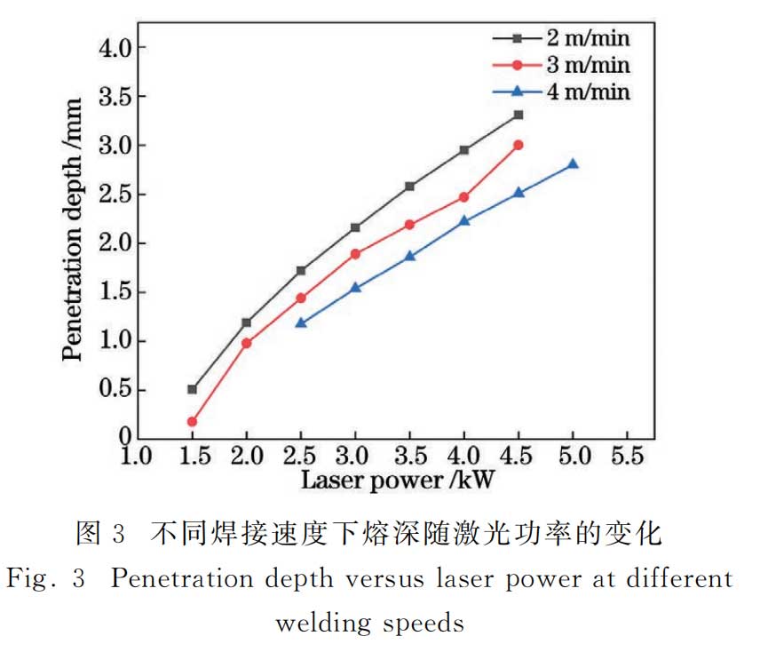
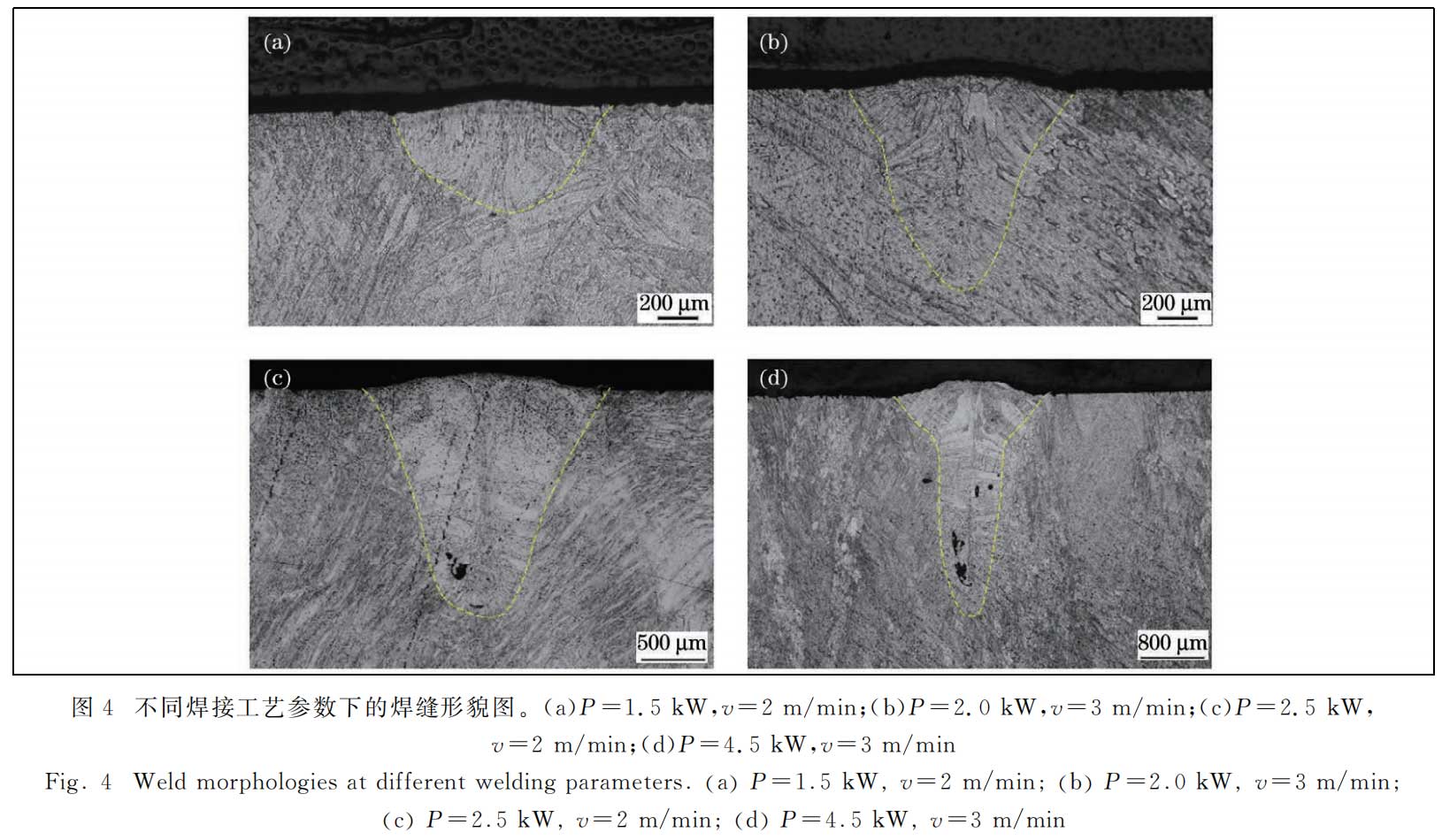
Under different laser power and welding speed conditions, the variation law of weld penetration is shown in Figure 3. Under the same power, the weld depth is negatively correlated with the welding speed; when the welding speed is constant, the weld penetration is positively correlated with the welding power. When the power is 1.5kW and the welding speed is 2m/min, the weld morphology is a wide and shallow arc [Figure 4(a)], and the weld surface penetration width is greater than the weld penetration depth, showing a typical thermal conduction weld morphology. When the power is 2kW and the welding speed is 3m/min, the weld morphology is shown in Figure 4(b). The weld depth is significantly greater than the weld surface width, and the overall weld morphology is conical. The weld morphology at this time shows the characteristics of deep penetration welding. When the laser power is 2.5kW and the welding speed is 2m/min, the overall weld morphology is also conical. The weld depth and weld width increase at the same time, and the weld depth is greater than the weld surface width. The weld morphology shows more obvious deep penetration welding characteristics. As shown in Figure 3, the slope of the curve of weld penetration with laser power in the range of 1.5~2.0kW is significantly greater than the slope of penetration after deep penetration welding, and the change of penetration is more significant, indicating that the welding mode has changed within this power range. When the laser power is 4.5kW and the welding speed is 3m/min, the weld morphology is shown in Figure 4(d). The weld depth-to-width ratio is large and the weld is in the typical "nail head" shape of laser deep penetration welding. The weld height under thermal conduction welding mode is small [Figure 4(a)], while the weld height under deep penetration welding with higher power is large [Figure 4(d)], which is related to the molten pool volume and flow characteristics under the two welding modes.
3.2 Analysis of butt welding test results
3.2.1 Macroscopic morphology analysis of the sample
According to the test results in Figure 3, when the laser power P=4kW, the welding speed v=2m/min, and the defocus f=0mm, the penetration depth is 3.0mm, so this parameter is used to carry out the 3mm thick Ta-10W butt welding test.
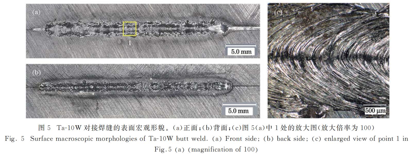
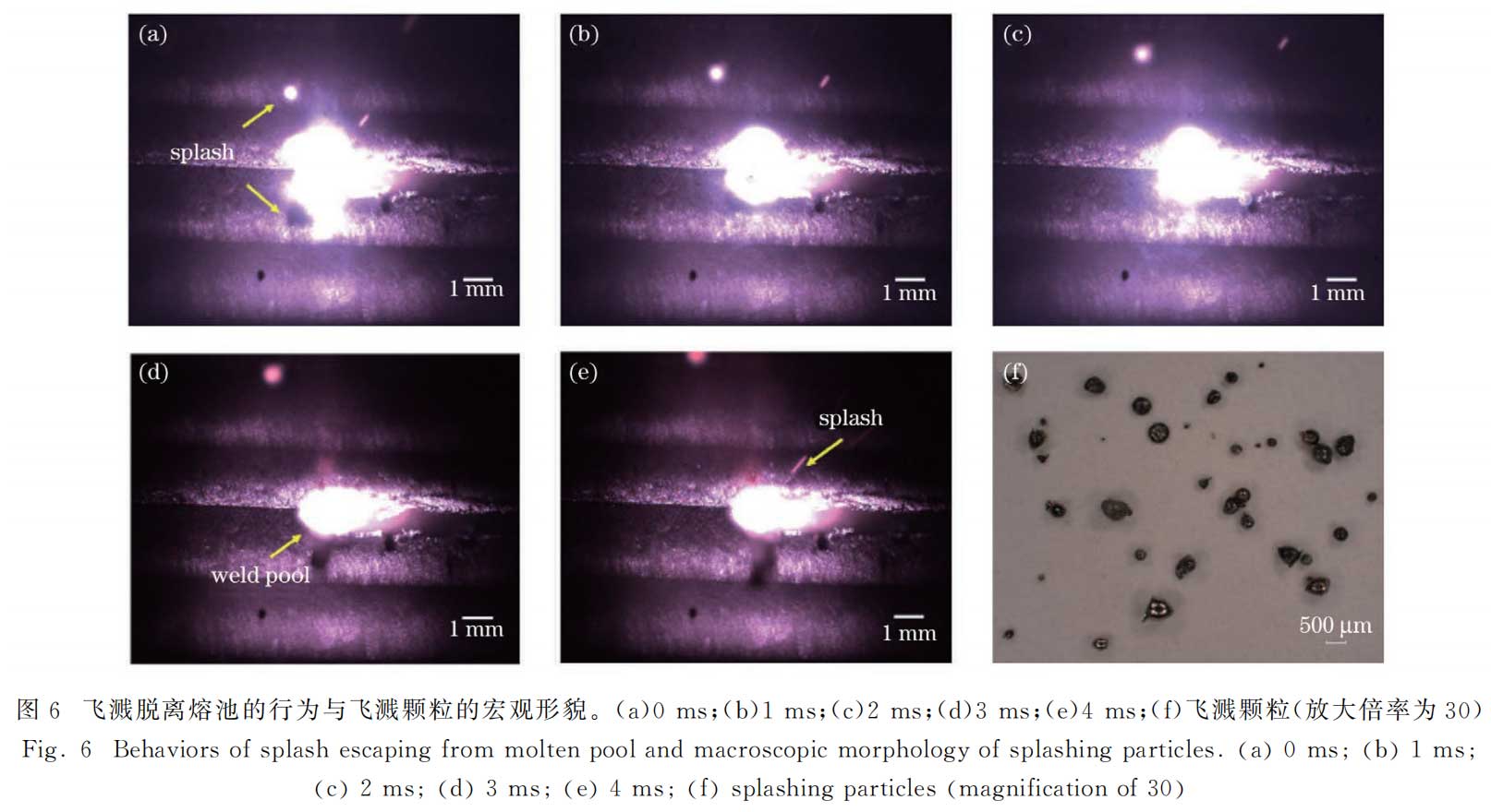
The surface morphology of the Ta-10W butt joint is shown in Figure 5. The weld is fully penetrated, the front of the weld is well protected and formed, the weld surface is bright white, and there is no obvious oxidation mark; the back surface of the joint is smooth, with slight convexity and no concave defects; the weld surface has obvious fish scales. Compared with the surface of aluminum alloy and high-temperature alloy welds, the fish scales are arc-shaped and the arc curvature is smaller [Figure 5(c)], which is related to the shorter length of the weld pool [Figure 6(d), (e)] and the physical properties of the high melting point of the parent material. It can be seen from the high-speed camera [Figure 6(a)~(e)] that the spatter is separated from the molten pool, indicating that the spatter is serious during the welding process, but there is very little spatter attached to the weld and the surface of the plate. After welding, the spatter particles are collected for observation. As shown in Figure 6(f), the larger spatter particles will oxidize after being separated from the protective atmosphere, and the surface will turn into blue and other oxidized colors; while the surface of a small number of smaller spatter particles maintains a bright color, and the spatter is mostly spherical particles. This is because Ta-10W has a high melting point, and the spatter has solidified when it falls on the weld and the parent material surface.
3.2.2 Microstructure Analysis of Butt Welds
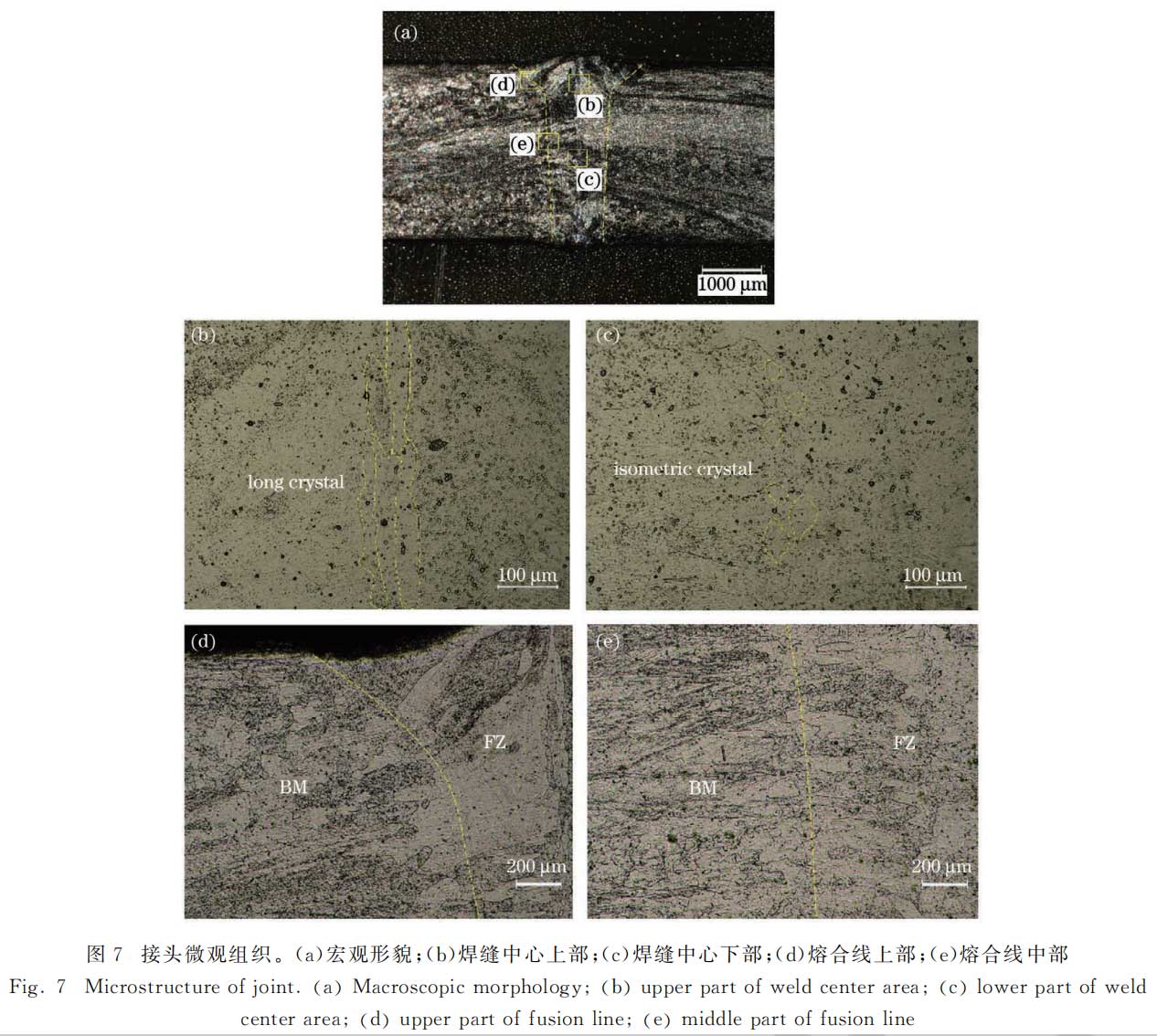
The macroscopic morphology and structure of the butt joint are shown in Figure 7. The weld joint is a typical nail head shape, with a surface melt width of 2.26 mm, and the lower width of the weld nail head part, i.e., the waist width, is 1.07 mm [Figure 7(a)]. Among them, BM is the parent material area, FZ is the weld area, and the weld structure is mainly columnar crystals. Comparing the structures at different positions in the weld center, it is found that the morphology and size of the grains at different positions in the weld center are quite different. Among them, in the upper position of the weld center, slender grains perpendicular to the plate thickness direction are formed, with a length of up to several hundred microns and a diameter of only tens of microns [Figure 7(b)]; while in the middle and lower positions of the weld center, fine equiaxed grains are formed, with a grain diameter of only tens of microns [Figure 7(c)]. From the partial enlarged image of the weld fusion line [Figure 7(d), (e)], it can be found that compared with the laser deep melting welds of materials such as aluminum, steel and high-temperature alloys, the fusion line of the Ta-10W weld is not obvious, and the position of the fusion line can only be determined by the fine recrystallized grains and columnar crystal growth direction near the fusion line [as shown in the dotted line of Figure 7(a), (d), (e)]. The main reason is that the Ta content (mass fraction) in the Ta-10W alloy is as high as 90%, and the viscosity of the melt in the molten pool is low and the fluidity is strong during welding.
3.2.3 Butt weld performance test and fracture morphology analysis
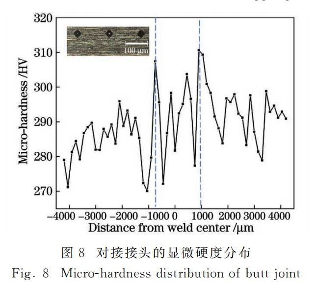
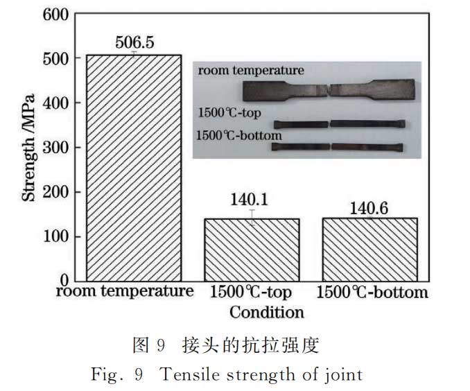
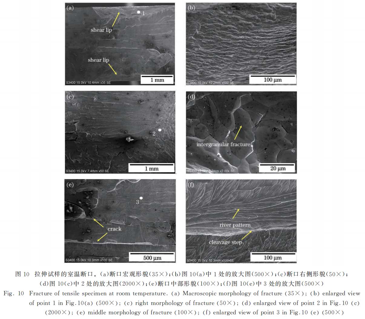
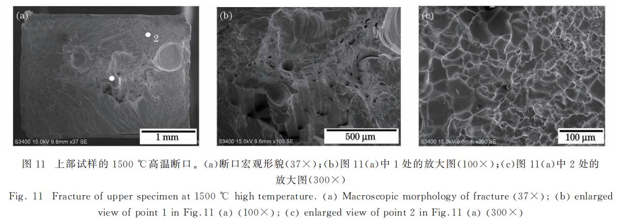
The microhardness of the Ta-10W butt joint was tested with a test force of 1.96N, a load time of 15s, a test position at the center of the plate thickness, and a test point spacing of 150μm. The test results are shown in Figure 8, and it can be seen that the microhardness of the weld area fluctuates greatly. Among them, the maximum hardness of the weld can reach 311HV, the minimum hardness is 271HV, the average hardness is 294HV, and the microhardness value of the parent material is basically around 280HV. The microhardness near the fusion line of the weld fluctuates most violently, which is related to the heating conditions and grain size refinement in the area near the fusion line. The mechanical properties of the welded joint are shown in Figure 9, where the upper right is a photo of the three specimens after being pulled apart. The tensile test results of the welded joint show that the room temperature average tensile strength of the joint is 506.5MPa, which is 92.1% of the room temperature tensile strength of the parent material (550MPa); when tested at a high temperature of 1500℃, the average tensile strength of the upper weld specimen is 140.1MPa, and the average tensile strength of the lower weld specimen is 141.6MPa. The specimens are all broken in the parent material, indicating that the Ta-10W laser welded joint has good room temperature and high temperature mechanical properties. The fracture morphology of the room temperature joint is shown in Figure 10. The fracture occurred at the weld, showing mixed fracture characteristics of intergranular fracture and cleavage fracture. The upper and lower edges of the fracture have obvious shear lips [Figure 10 (a)], with a smooth surface and dark color. The shear lips of the fracture are roughly 45° to the tensile direction. Under high magnification, this part of the material undergoes obvious plastic deformation [Figure 10 (b)]. The left and right sides of the fracture are rough and uneven [Figure 10 (c)]. Under high magnification, a typical rock candy-like pattern can be seen [Figure 10 (d)], indicating that intergranular fracture has occurred. In addition, there are typical cleavage facets, cleavage steps and several cracks in the middle of the fracture [Figure 10 (e)]. Under high magnification, a typical river pattern can be seen [Figure 10 (f)], indicating that cleavage fracture has occurred at this location. The high-temperature fracture morphology of the weld is shown in Figures 11 and 12. Among them, the high-temperature fracture morphology of the upper weld sample shows that many large and deep plastic dimples are generated in the middle area of the fracture [Figure 11(a)], accompanied by obvious slip phenomenon, and there is no obvious interface between grains [Figure 11(b)]; the tiny pores in the parent material are deformed under the action of external force and become irregular elliptical; the radial area around the cross section is mainly a rock candy-like intergranular fracture morphology under high magnification, with some transgranular fracture characteristics, the grain boundary is clean and smooth, and there is no precipitate phase distribution [Figure 11(c)].
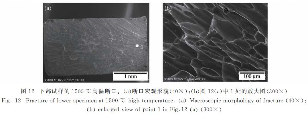
The high-temperature fracture morphology of the lower weld sample is shown in Figure 12. Compared with the fracture of the upper sample, there is no pore defect on the fracture surface, and the whole presents a radial pattern [Figure 12(a)]. This is because the crack source is located on the surface of the sample, and the crack expands under the action of tension, which finally leads to this fracture morphology. Under high magnification, the fracture mainly presents a rock candy-like intergranular fracture morphology. The grains are elongated under high temperature and external force, and are significantly deformed [Figure 12(b)].
4 Conclusion
The threshold curve of fiber laser deep penetration welding of Ta-10W material was obtained. Due to the high melting point physical properties of the material, the molten pool is small during deep penetration welding, and the weld presents a nail head morphology. When the focus spot diameter is 0.3mm and the welding speed is 2~3m/min, the critical power range of Ta-10W multimode fiber laser deep penetration welding is 1.5~2.0kW. When the laser power is 4kW and the speed is 2m/min, the 3mm thick Ta-10W butt joint is well formed. Along the depth direction of the weld, the grain morphology at the center of the weld is quite different. The upper part of the joint is slender grains, and the middle and lower parts are equiaxed grains. WeldThe microhardness of the weld is slightly higher than that of the parent material. The room temperature tensile strength of the weld is 506.5 MPa, which is 92.1% of the tensile strength of the parent material, and the fracture shows mixed fracture characteristics; the high temperature tensile strength at 1500 ℃ is about 140.9 MPa, which is 25.6% of the room temperature strength of the parent material, and the fracture shows typical intergranular fracture characteristics. The research results show that in the atmospheric environment, the use of fiber laser can achieve effective connection of refractory alloys such as Ta-10W.
About Stardust Technology
Stardust Technology (Guangdong) Co., Ltd. is a national high-tech enterprise specializing in the research, development, production and sales of high-end spherical powder materials for 3D printing, powder metallurgy, surface engineering and other fields. The company insists on taking radio frequency plasma spheroidization powder making technology as the core, and provides internationally advanced powder products and application solutions.
The company's main products include high-end rare refractory metals such as tungsten, molybdenum, tantalum, niobium, vanadium, rhenium, chromium and their alloys, compound spherical powders, and also provide technical services such as radio frequency plasma spheroidization, plasma rotating electrode atomization, 3D printing, hot isostatic pressing, injection molding, powder metallurgy, etc.
The spherical Ta-W refractory alloy powder produced by Stardust Technology is made by radio frequency plasma spheroidization atomization method. It has the characteristics of high purity oxygen deficiency, high sphericity, smooth surface, no satellite, uniform particle size distribution, excellent flowability, high loose density and high vibration density. Tantalum tungsten alloy is a high-density material with high melting point, high tensile strength, good dynamic ductility and corrosion resistance. It is used in chemical corrosion protection, machinery, aerospace and military fields.
https://www.stardustpowder.com/spherical-ta-w-alloy-powder

Please contact us for more details

Paper citation information
Volume 49 Issue 16/August 2022/China Laser Research Paper
Chinese Library Classification Number TG442 Document Code A DOI:10.3788/CJL202249.1602006